Sunday, December 30, 2012

Fireworks Controller

My brother-in-law puts on a hell of a fireworks show every year for New Years. Last year he upgraded to electronic ignitors so that he could fire them from 50-60 feet away. His system consisted of a 12v battery pack from a PowerWheels(r) car and two planks of wood with several nails punched through each. The nails were each wrapped with a couple turns of speaker wire that ran out to his ignitors, and the other leg came back to a central positive terminal that connected back to the battery. Not super elegant, but very effective and easy to troubleshoot and control.

I decided this year he deserved a better system to trigger his ignitors. So I built him this:

This ignition system has 24 channels or "queues", an internal power supply, and it looks pretty sweet too.

My parts for this build were pretty simple:

  • 1/4" MDF (get 1/8", or use Paneling...the 1/4" MDF has an issue, see below)
  • 24 momentary contact push-buttons
  • 48 LEDs (24 green, 24 red)
  • Key switch
  • SPDT switch (with the red switch cover)
  • 12 speaker terminals (each terminal has hookups for 2 ignitors, using 4 terminals)
  • 12v LED strip from auto-parts store
  • 12v battery
  • Pretty case

First off I started with a blank piece of 1/4" MDF I purchased from Home Depot.This served as the base board for the electronics. I decided on a layout for the controls, and then using my drill press and my eyeballs I put the 24 holes for the push-buttons and then used a hand drill for the LED holes.
At this point my MDF looks like this.

I then used my Dremel tool with a router bit to free hand the slots for the speaker terminal connections. I am not a carpenter, nor to I claim to have any sort of artistic capability...this part is utilitarianism at its best.

It was at this point that I *noticed* my MDF was too thick for the buttons and switches to mount to without modification...so at this point I broke my Dremel back out and cut recesses around EVERY SINGLE button hole to reduce the thickness from 1/4" down to around 1/8". This was where I lost about 2 hours on my build, because these recesses had to be done free-hand, and it generated copious amounts of dust.

I painted the front of the board a brownish color because that is what I had handy. Next time maybe it will be black, or a high gloss silver.


Then I started mounting components. I started with the push-buttons and then the LEDs. The push-buttons had nuts to hold them down, and for the LEDs I just used a touch of super-glue right at the edge and it worked great. The speaker terminals and other switches were very simple to mount. This left me with a very pretty front panel (ignore the fact that I can't measure and things are a bit crooked).
Now I started wiring up the components. There are basically two circuits going on here. A Test Circuit, and a Live/Fire Circuit.

The schematic is pretty simple:
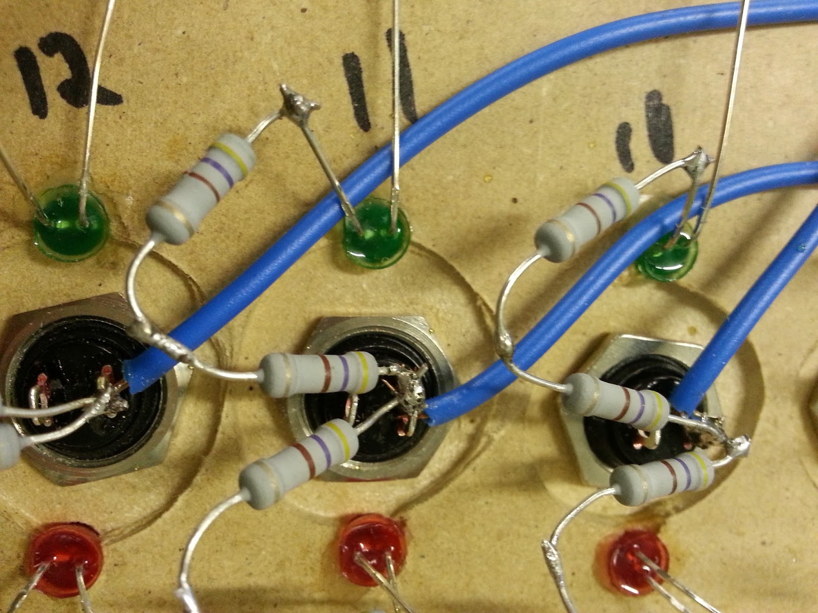
From the primary switch (key-switch) tie in each green LEDs long leg (positive). I used simple jumpers for this. I thought about etching up a PCB for this purpose, and I would if I had a little more time, but for this prototype I just jumped them all together. From the short leg of the green LED I ran the two 470ohm resistors in series, then tied that to the red side of the speaker terminal. I then tied all of the negative speaker terminals together and tied that back to the negative side of the battery.

This may not sound like much but after that step my wiring was getting a little cluttered:

I'm not the best solderer in the world, but I was kind of proud of how well this simple design was manifesting.

I also tied in a 12v LED module into the key ignition so that we could have a little light while hooking the ignitors up, plus it adds a pretty blue glow and also serves as a "power" indicator.

At this point I needed to mount the board in the case, and hook up the battery, and I was in good shape.
Some shots of the finished prototype are below.


If you have any questions or need more information, email me. jamesbradleyharris@gmail.com

Sunday, November 1, 2009

Ghetto Delta Robot

I started building a delta robot a few days ago with the intention of using it as a starting point for a more complex robot down the line. Life has progressively gotten in the way, but I wanted to share my status partly in hopes that it will push me to continue making progress, and also maybe to inspire someone else.

First off, I’m using an Arduino to control the servos. The actual calculations are done in Processing on the PC, and sent over to the Arduino through serial as a set of angles for the servos to hit. Eventually, I’d prefer to send more basic commands (X, Y, and Z) over the serial and have the Arduino do the math to calculate the required angles.

As part of my self-imposed limitations, I’ve decided to keep costs as low as possible, since eventually I will be building 4 more of these to finish out the prototype ground soldier for my future robot army.

SNC00180SNC00185

SNC00182SNC00184

So far I have the servos, Arduino, custom interface board, and wiring in place. The servos are mounted around the perimeter of a CD. I was looking for something rigid, light, and about 5” diameter. It turns out a CD works perfectly, and at a cost of about $.40, it fits into my cheap critera as well.

SNC00189 SNC00192

I’m working out the armature so that I can keep the whole thing light but strong. I’ve gone with 5/64” aluminum wire. This can easily be obtained from (of all sources) ordinary wire coat hangers. This stuff is flexible enough to be easy to work with, but at lengths less than 7” it is strong enough to hold shape against most reasonable stresses. I bent the wire with 3x90deg angles to form a sort of hook, then using a drill I widened the holes in the servo arms to accept the wire. This holds it well enough, but to make sure it didn’t flex laterally while in use, I added small zip-ties to add a little extra security.

Next up I hope to finish the arms, and mount a small plate at the top that will support a stepper motor, worm gear, and some sort of rubber tire.

So far, with the servos and Arduino, my total costs for this project are right around $75. If you got the same (or slightly better) servos online instead of Hobbytown, this could easily be put closer to the $50 mark. I already had the CD, coat hangers, hot glue, wires, solder board, and the various other pieces I needed. I expect to finish this project for less than $100.

I’ll post more as I have time to make progress.

Thursday, October 29, 2009

Blindspot Sensor Work II

New parts! I got two new sensors that are supposed to have a 6.25 m range. I've got two sensors working at the same time. There's some instability in the measurements, but I think that might be a function of driving the Arduino board off the USB cable. It also prevented me from testing the sensors and motor together.


 Brad also came through with an Arduino motor shield, but I'm not quite ready to start soldering to the board. I'm found some Arduino 6 and 8 pin spacers, so I'm going to wait for those to show up before getting started on driving the 2 motors.

I've also started reworking the notification logic. We started with a constant notification logic. Whenever something was in range of the sensor, we would drive the motor. We then increased the motor speed with proximity. This didn't work well in practice. The motor wasn't big enough to give good gradation over the range, and the always on quickly became annoying. It stopped being information.

The new logic plan is to have 3 zones: near, medium, far (and technically a fourth -- out of range). Each zone will have an initial notification pulse, and then a delay. Basically, if an object remains in the same zone or moves to a further zone, we will skip a couple of notification cycles. I didn't get very far on thtat. That's this weekend's project.

Sunday, October 25, 2009

Test Drive I

After driving around a little bit today, I have the following observations:
  1. It WORKS!!!
  2. 3m is not long enough range to give enough warning to do anything. I am looking into some 6.5m sensors with a wider range.
  3. We probably need bigger motor. The signal can get lost in the vibration of the car, especially at the outside edge of the range. 
  4. I'm not sure our test lumbar is going to allow us to differentiate between left-side and right-side inputs. We can certainly put 2 motors in there, but I don't know that the signal will be distinct because it is essentially all 1 foam piece that gets jiggled.
So, not a bad test run. I'm going to get on Sparkfun and see about ordering new parts.

Haptic Blindspot Sensor I

Brad took my idea of a haptic blindspot sensor for the car and started to run with it a couple of weeks ago. Using an Arduino Duemilanove controller board, an ultrasonic sensor with a 3m range, and a little variable speed motor, we were able to prove that we had enough hardware on hand to put together a prototype.

Last night, Brad and I spent about 5 hours working on the first prototype. Brad wired up a car lighter adapter to power the thing. We used 4 wire telephone cable and audio jacks to modularize the 3 parts (sensor, controller/power, and motor). Some parts weren't pretty. (There's probably a better way of cutting the prototype boxes than using a Dremel.) However, we persevered and got something built.


This morning I went by Walmart and found a massaging lumbar support with 3 massage points for about $20. I ripped out one of their motors, put our motor in the housing, and tested. Everything worked.

After that, it was a simple matter of mounting the sensor to under the left rear bumper using some double sided tape. I was able to run the cable behind the bumper. My car happens to have an electrical housing that goes out through the spare tire well. I was able to plug in to an outlet in my cargo space. Everything sits in one of the floor storage compartments.


Now for the first drive!